AYA5 decoupling capacitors?
Quote from Chris on 12 November 2024, 2:48 PMFirst: sorry if this has all been discussed/explained before. I could not find any information here.
I see in pictures that AYA5 (I believe S5 too) has smd decoupling caps. There are lots of different opinions regarding decoupling caps. Some designs even use electrolytic capacitors with as high as 100nF values. See here:
TDA1541(A) Dynamic-Element-Matching Slowed Down - MV Audio Labs
MV-Audiolabs tells, that their electrolytic caps design needs to "burn in" for 20 min everytime you turn off the DAC for 24 hours. That looks like a big drawback to me.
I don't know a lot about electronics. So, no need to write a long technical explanation for me but I would be interested Audial's philosophy concerning decoupling caps.
First: sorry if this has all been discussed/explained before. I could not find any information here.
I see in pictures that AYA5 (I believe S5 too) has smd decoupling caps. There are lots of different opinions regarding decoupling caps. Some designs even use electrolytic capacitors with as high as 100nF values. See here:
TDA1541(A) Dynamic-Element-Matching Slowed Down - MV Audio Labs
MV-Audiolabs tells, that their electrolytic caps design needs to "burn in" for 20 min everytime you turn off the DAC for 24 hours. That looks like a big drawback to me.
I don't know a lot about electronics. So, no need to write a long technical explanation for me but I would be interested Audial's philosophy concerning decoupling caps.
Quote from Pedja on 13 November 2024, 12:19 PMTo answer most shortly, both AYA 5 and S5b use 100 nF for DEM decoupling. So, "as recommended by Philips".
Chronologically speaking, when I started designing with TDA1541A, I used 2.2 uF for MSB and 100 nF on other DEM pins, and later, while Black Gate (NX) caps were still regularly available, I have been using 470 nF at all DEM pins, because their pattern was the same as that of 100 nF NX, so more capacitance came "for free".
Then, since 2007, all Audial TDA1541A DACs have used 100 nF PPS SMD caps at all DEM pins.
As for the philosophy:
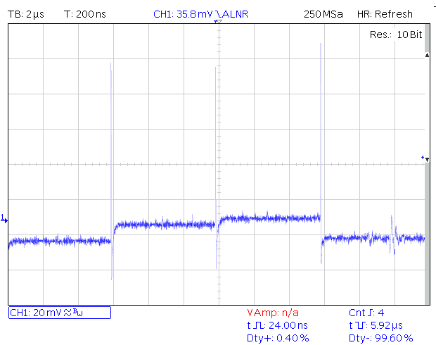
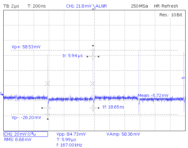
First, if you look at the "raw" waveform at DEM pins, you can notice the "sequence" made of four parts, each belonging to one of four primary current sources, effectively forming Fdem/4 spurious signal, and 15-20 ns wide and 20-150 mV high switching spikes, occurring each time these currents interchange.
Each DEM pin has somewhat characteristic spikes and Fdem/4 fluctuation levels, but what is interesting here is that the MSB pin does not have the highest level of spurious content, as commonly believed. For instance, the scope shot below shows how this sequence looks at the unfiltered MSB-2 pin, where the glitches were the highest (HSH9305 sample).
And here is the unfiltered MSB pin of the same chip.
So the purpose of these caps is to filter out these irregularities, and in my view, the spikes are more important than the Fdem/4 frequency itself, because that part is more "tame" and its level is lower. Hence, the caps should be chosen for their HF performance in the first place, yet 100 nF attenuates notably the Fdem/4 frequency too, so long as DEM frequency is kept within Philips recommendations. At 40 kHz (DEM running at 160 kHz), with 5k "median" impedance at DEM pins, a 100 nF attenuates for about 40 dB (i.e. 100 times).
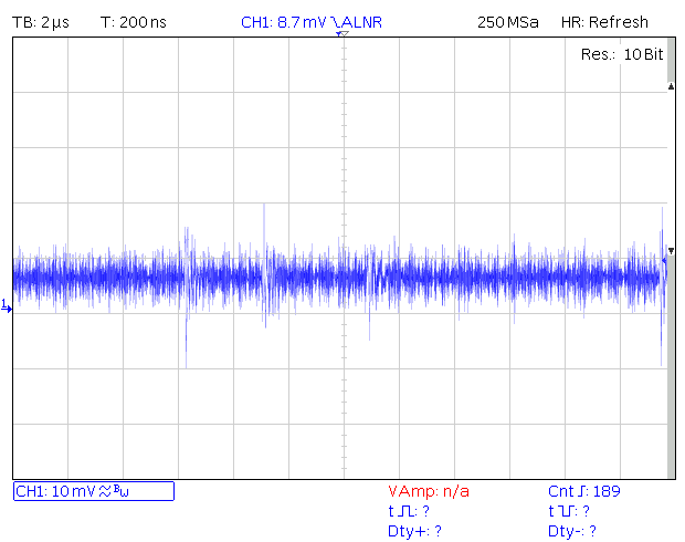
Unfortunately, at this moment, I can not find a useful graph to display the results. The only one I could dig can only confirm that the spurious content got attenuated enough to fall below the residual noise of the measurement setup used also for the above graphs (you can estimate yourself how high it is). If you find it to be useful, I can also make and post later more fine measurements by using a differential probe.
The article you linked above is an interesting reading and experiment, and the use of a notably higher capacitance is obviously associated with lower DEM frequency. As a solution, this does not look appealing to me, though, because the compromises introduced both by the DEM frequency moved within the audio band, and by the use of the electrolytic caps here (their HF performance is surely inferior, and their leakage current change over time has both good and bad parts – 20 minutes later they may perform better, but two years later they may perform worse) are for me not justified.
Your (or other's) preferences may vary.
To answer most shortly, both AYA 5 and S5b use 100 nF for DEM decoupling. So, "as recommended by Philips".
Chronologically speaking, when I started designing with TDA1541A, I used 2.2 uF for MSB and 100 nF on other DEM pins, and later, while Black Gate (NX) caps were still regularly available, I have been using 470 nF at all DEM pins, because their pattern was the same as that of 100 nF NX, so more capacitance came "for free".
Then, since 2007, all Audial TDA1541A DACs have used 100 nF PPS SMD caps at all DEM pins.
As for the philosophy:
First, if you look at the "raw" waveform at DEM pins, you can notice the "sequence" made of four parts, each belonging to one of four primary current sources, effectively forming Fdem/4 spurious signal, and 15-20 ns wide and 20-150 mV high switching spikes, occurring each time these currents interchange.
Each DEM pin has somewhat characteristic spikes and Fdem/4 fluctuation levels, but what is interesting here is that the MSB pin does not have the highest level of spurious content, as commonly believed. For instance, the scope shot below shows how this sequence looks at the unfiltered MSB-2 pin, where the glitches were the highest (HSH9305 sample).

And here is the unfiltered MSB pin of the same chip.

So the purpose of these caps is to filter out these irregularities, and in my view, the spikes are more important than the Fdem/4 frequency itself, because that part is more "tame" and its level is lower. Hence, the caps should be chosen for their HF performance in the first place, yet 100 nF attenuates notably the Fdem/4 frequency too, so long as DEM frequency is kept within Philips recommendations. At 40 kHz (DEM running at 160 kHz), with 5k "median" impedance at DEM pins, a 100 nF attenuates for about 40 dB (i.e. 100 times).
Unfortunately, at this moment, I can not find a useful graph to display the results. The only one I could dig can only confirm that the spurious content got attenuated enough to fall below the residual noise of the measurement setup used also for the above graphs (you can estimate yourself how high it is). If you find it to be useful, I can also make and post later more fine measurements by using a differential probe.

The article you linked above is an interesting reading and experiment, and the use of a notably higher capacitance is obviously associated with lower DEM frequency. As a solution, this does not look appealing to me, though, because the compromises introduced both by the DEM frequency moved within the audio band, and by the use of the electrolytic caps here (their HF performance is surely inferior, and their leakage current change over time has both good and bad parts – 20 minutes later they may perform better, but two years later they may perform worse) are for me not justified.
Your (or other's) preferences may vary.
Quote from Chris on 13 November 2024, 9:03 PMThank you for the detailed explanation. One can see that you have thourough knowledge of the TDA1541 and years of experience. I cannot afford the S5 but I think I will go for a AYA5 which is just at the limit of what I can afford.
Are the actual AYA5's still fitted with a taiwanese TDA1541 from the nineties?
Thank you for the detailed explanation. One can see that you have thourough knowledge of the TDA1541 and years of experience. I cannot afford the S5 but I think I will go for a AYA5 which is just at the limit of what I can afford.
Are the actual AYA5's still fitted with a taiwanese TDA1541 from the nineties?

